LINDSEY RACING INTAKE MANIFOLD INSTALLStep 1 - Remove Stock Intake ManifoldStep 2 - Blocking off Water Thermal Switch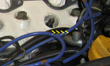 At the back of the cylinder head is a metal water routing tube for the heater. In stock configuration, it has a thermal switch screwed into the hole shown. We suggest you remove the switch and install the supplied plug. Put some Teflon thread tape on the plug before you install it. Connect the vacuum lines that used to run through the switch together. You can use a 90 degree fitting and move the switch over and out of the way, if you like, but we do not supply the hardware to do this. Step 3 - Re-Positioning the Idle Air StabilizerYou first have to make the decision whether or not to use the Idle Stabilizer. If you have a dedicated track car, we recommend you remove it completely. If it's a street/track or street car, with A/C and driven daily, particularly in climates where you will have cold weather start up, we recommend you keep it. It will be necessary to re-position the piece to clear the underside of the intake plenum. With the stock intake removed, locate the Idle Stabilizer. Disconnect both hoses. The hose that runs to the intake between the runners will be re-used. The hose running to the intercooler pipe will be replaced with the supplied Purosil Silicone hose. Remove the 13mm hex bolt that attaches the bracket/pedestal to the engine block. From there, remove the two 10mm nuts that attach the band clamp to the bracket/pedestal. Loosen the band clamp and remove the Idle Stabilizer from the band clamp. Next we will modify the band clamp. We will need to drill out one of the holes at the base to allow for an 8mm bolt to pass through the hole (the bolt you removed earlier holding the bracket/pedestal). The best hole choice would be the one opposite the side you would tighten the band clamp on. Next, you can, if you like, saw off the other leg of the band clamp clear back to the round portion. You could leave it intact, but it makes for a cleaner installation if you remove it. A hack saw will remove it in a matter of seconds. Clamp in a bench vise to allow for easy cutting. We will be clamping the Idle Stabilizer on the smaller end of the part. It will be necessary to wrap the small end of the Idle Stabilizer with some electrical tape or equivalent to enlarge the diameter. Wrapping 5 or 6 times around with electrical tape is sufficient. 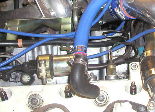 Position the Idle Stabilizer in the Band Clamp as Pictured and re-install the bolt to the engine block. The arrow on the housing of the Idle Stabilizer should be pointing to the hose that will connect to the intake manifold. Place the small original hose back on the Idle Stabilizer and have it sticking straight up and tighten the hose clamp on the Idle Stabilizer. From there, push the Idle Stabilizer slightly down and towards the head, bending the bracket into its final resting position. It won't move far, we're just trying to gain another 1/4". Install the Blue Purosil hose and clamp on the other hose barb on the Idle Stabilizer and run towards your intercooler pipe. Re-connect your wire connector and you're done. Time for the new intake. When you're done, the Idle Stabilizer will reside as it does in this picture. 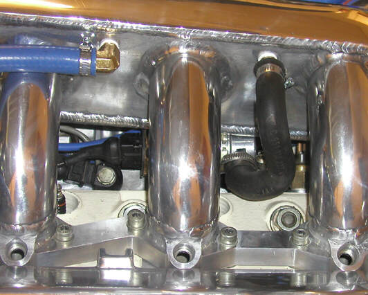 Step 4 - Installation of the Oil Dip Stick< 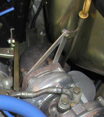
|
Secure Checkout


